


The Skim Reaper was a team project for my capstone engineering design course here at UMD. It is an autonomous algae skimming robot for small lakes and ponds. I helped develop this over the course of one semester, as part of what was hands-down the most capable and motivated team I've ever been a part of (names and links down at the bottom), and our final product/presentation won first place in the spring 2016 mechanical engineering capstone design day competition against 29 other teams. One of my team members, Chris Sneeder, put together the video below that shows a bit of an overview of the design, and some of the preliminary testing, but it's made to be talked over, so you'll have to interpolate a bit. Further down the page, I have some sexy exploded views, FEA, renderings, etc. so even if you aren't a big fan of reading, you should still Skim on down. If you're a "words" guy/gal, and you'd rather get the unabridged version of all this, you can download our final paper here.
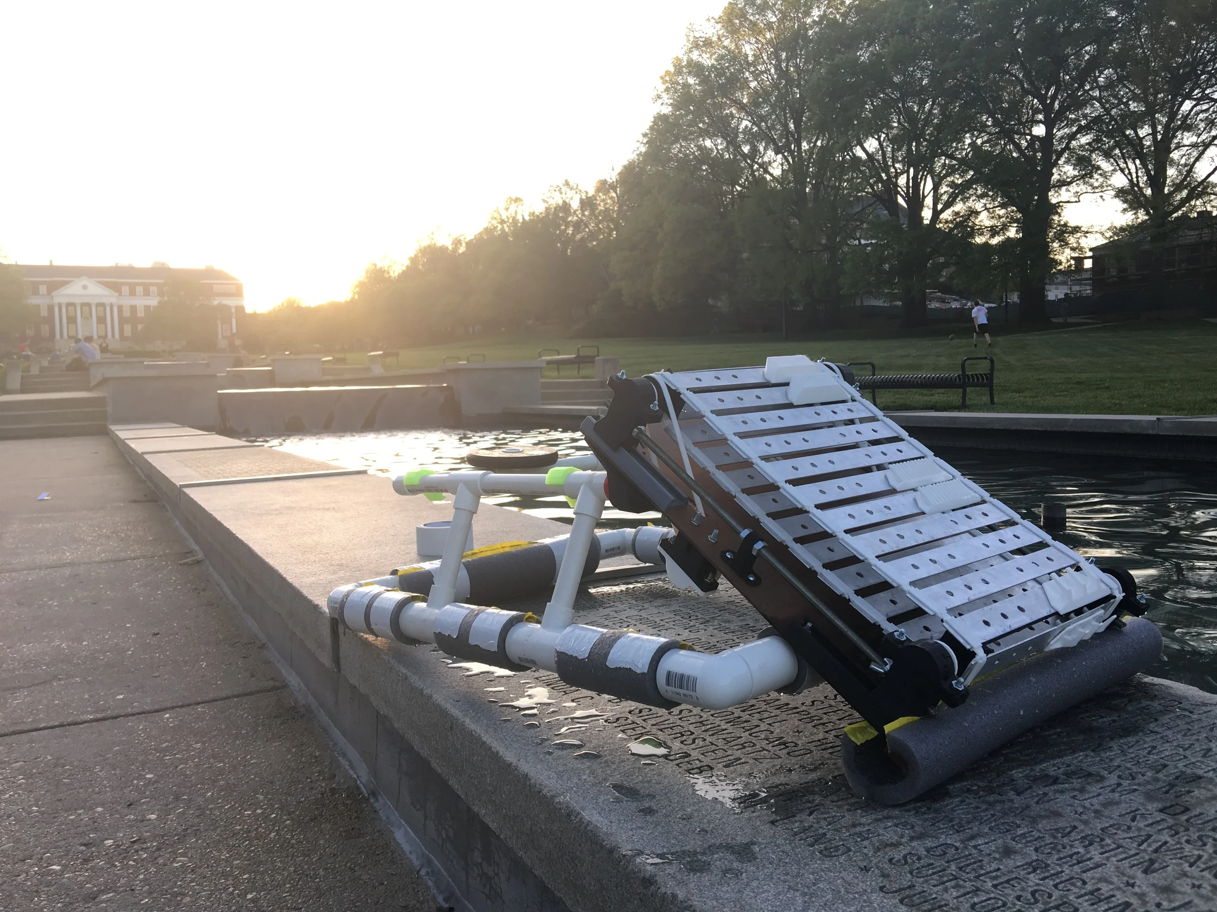
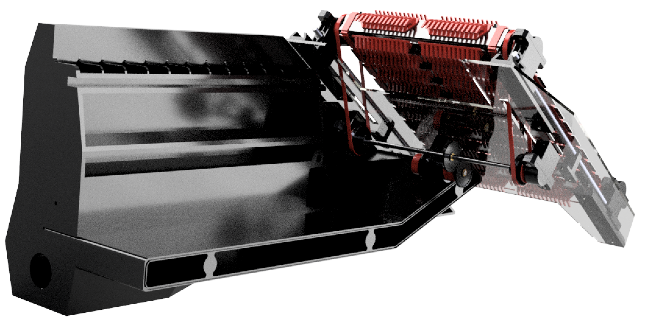
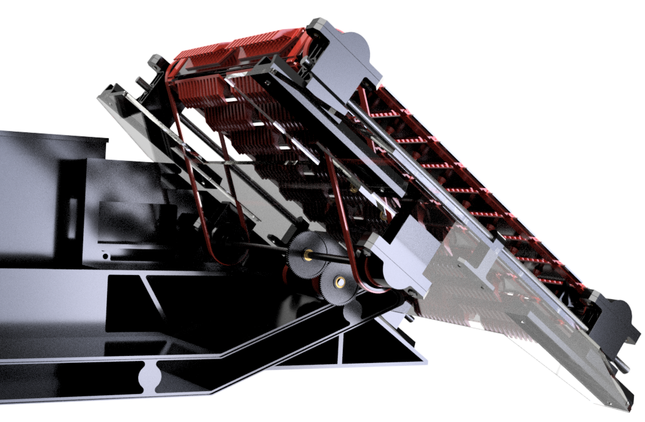
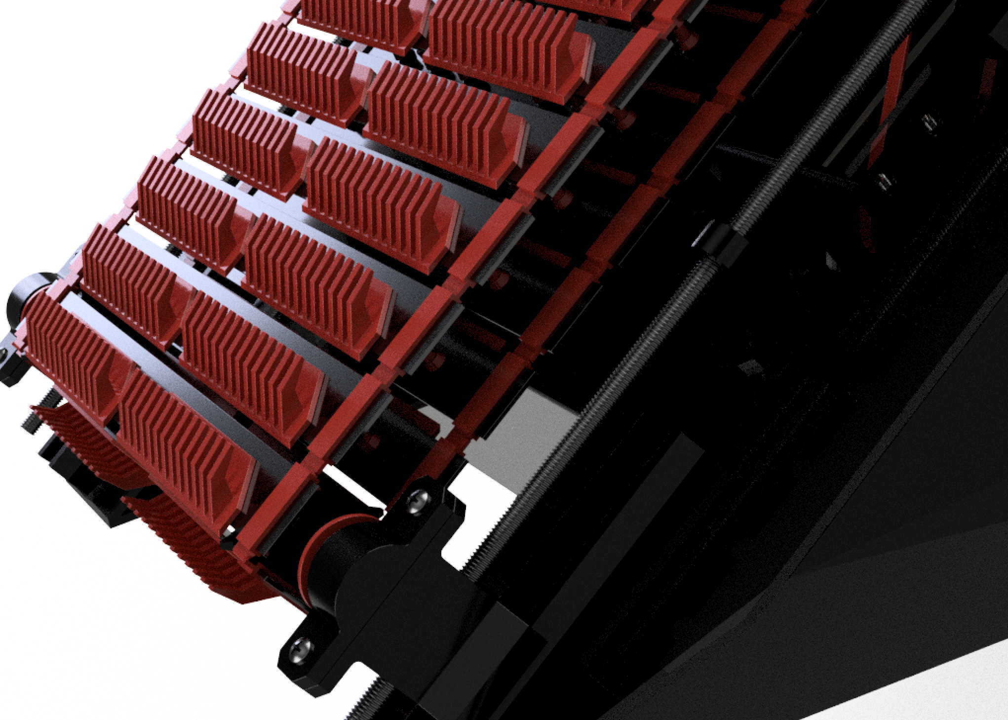
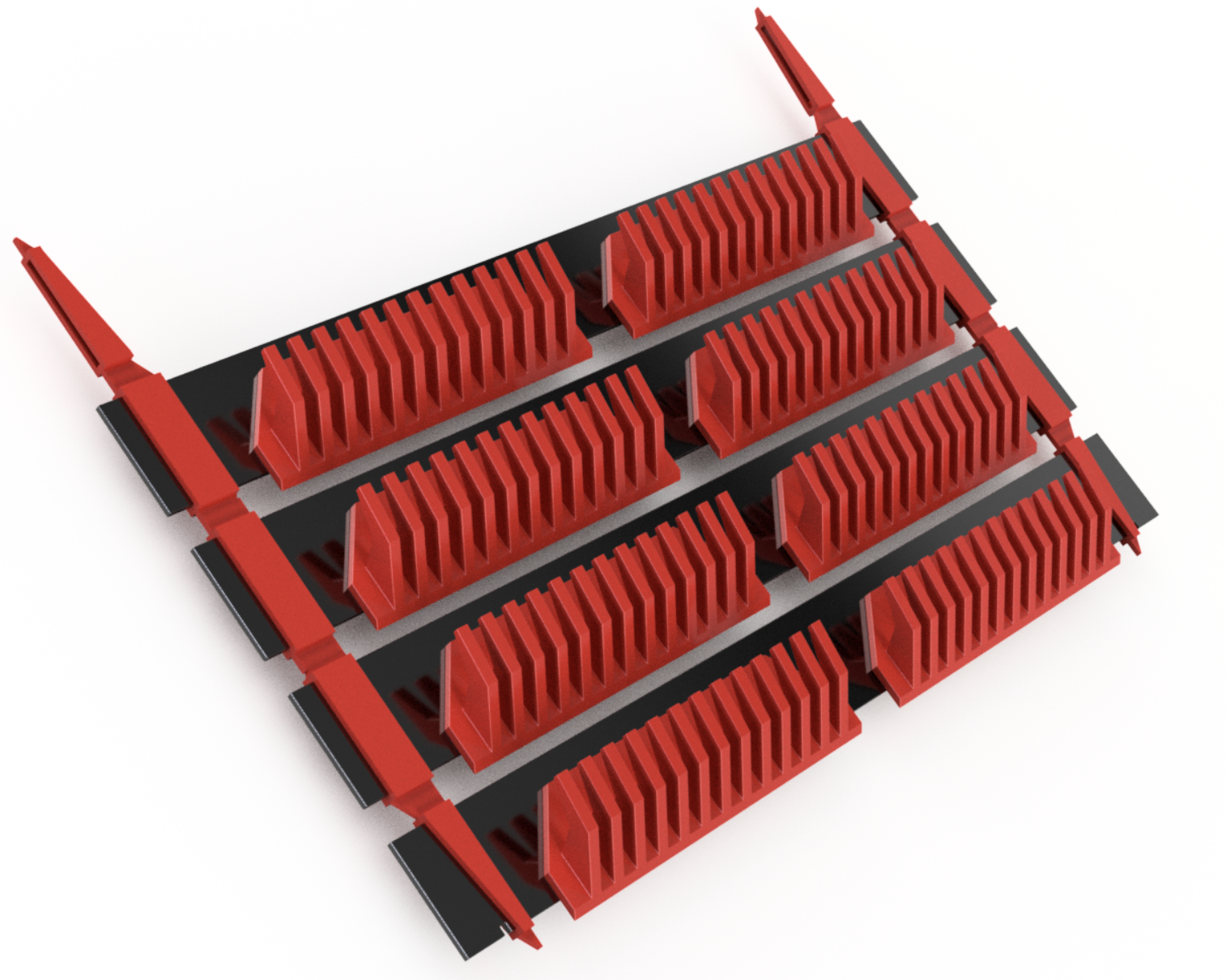
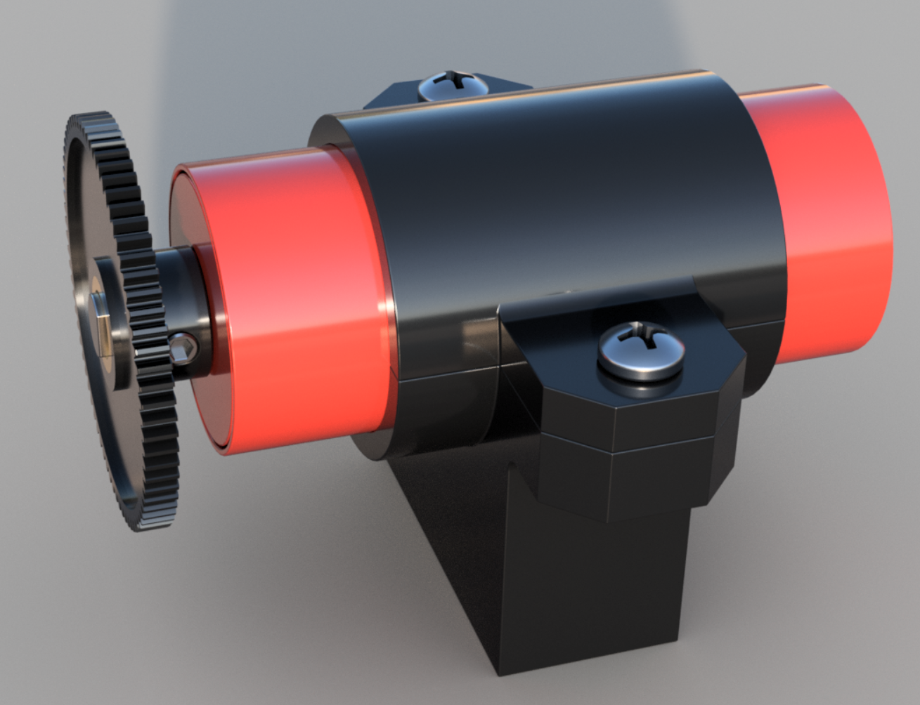
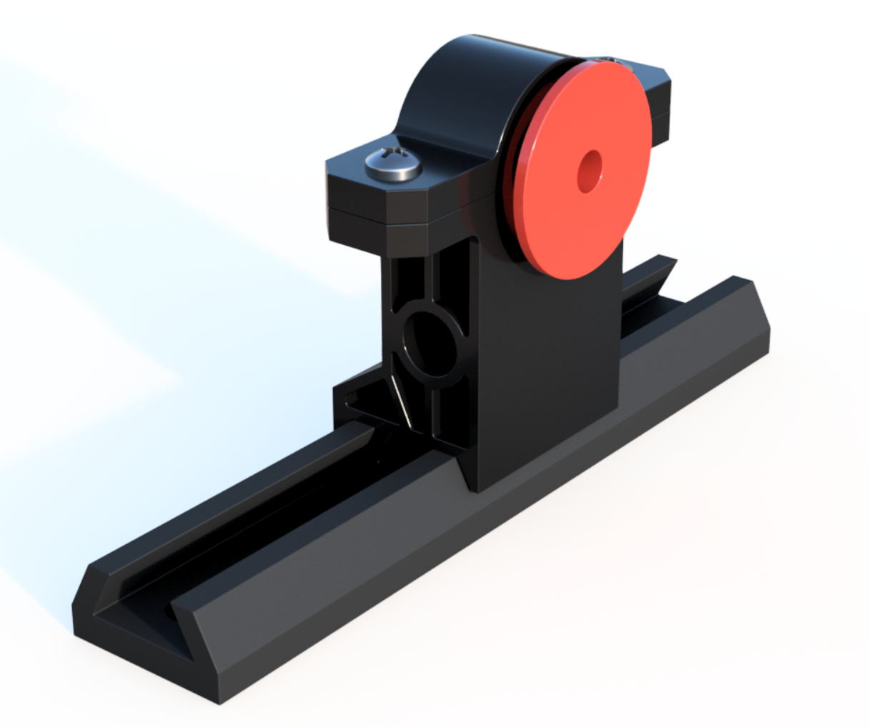
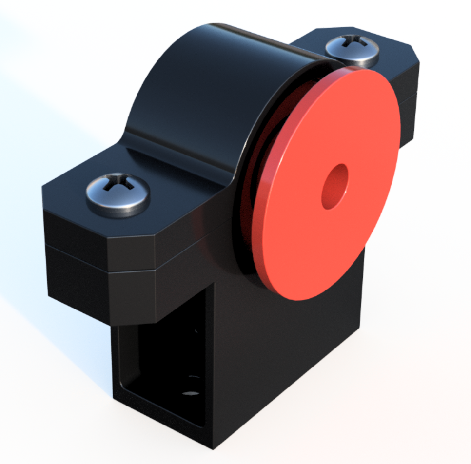
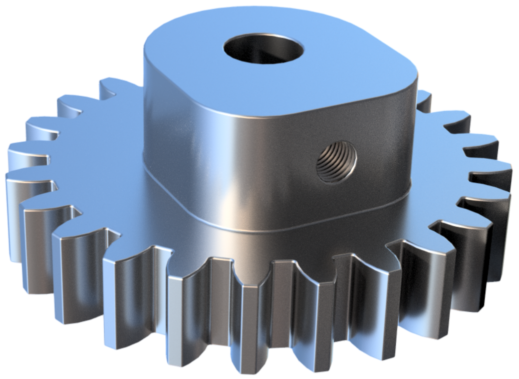
Let me explain a bit of what you're seeing there. The conveyor belt design is adjustable and modular, with threaded tensioning rods on either side that allow independent tightening of the drive belts and the conveyor belt. The aluminum slats are held together with flexible 3D printed belt couplings with a notch and detent system holding them in place, so any slat can be pulled out and replaced quickly and securely. The claw-like collection modules on the slats can be altered and popped in and out to pick up different types of surface vegetation. I also figured out how to work in a sliding dovetail joint (when in doubt...) as part of the belt-tensioning mechanism, so I consider that a success. The whole conveyor is driven by a motor beneath the mounting plate, which uses gears to drive a shaft that turns the two drive belts shown in red in the CAD. The whole assembly clips in place on the frame, which is made of PVC, and the wiring is routed through the piping. Below, I have a couple pictures of the completed prototype 1. You may notice that at this point, we had no propulsion.

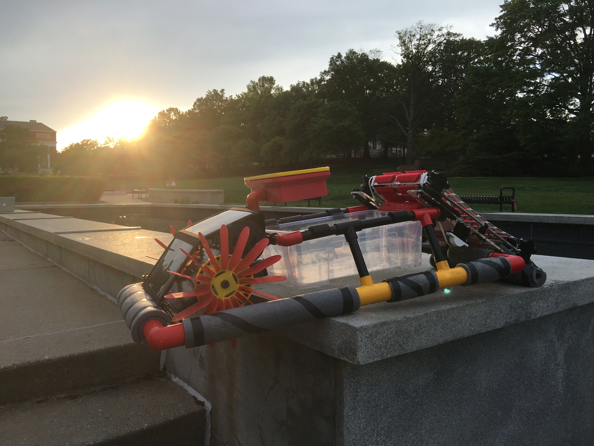
We made a mistake with the propulsion. We bought some of the worst components I've ever seen. These jet propellers were so terribly made that we scrapped the whole idea of using them after about an hour of trying. The injection molded components were complete garbage, they were still shooting molds that have been worn out for quite a while, and the soldering job on the smoothing caps appears to have been done by Edward Scissor Hands, with a TIG welder. Suffice it to say we weren't happy with the construction, or the loud, clattery 4A+ draw, and switched gears quickly to paddle wheels. The new design allowed us to use a geared motor, relatively far away from the water, and it made the Reaper quieter, and most importantly it made it look pretty shweet.

I would include a video, to show you how fast it went, but it's actually going notably faster in the still image. So we needed to change some things. We got some speedier/beefier (60 RPM) motors, mounted them in adjustable housings, modified the motor gears with flanges to hold the paddle wheel gears in alignment, cut the PVC to bring everything closer to the center, and gave the paddles themselves about 3x the surface area of these. Let's try this again:
Much better. Still no Dale Earnhardt Jr., but fortunately the algae isn't too speedy either, and the conveyor can keep pace with the propulsion. It's also worth noting that the GPS module was not installed at the time this video was taken (clearly that means navigation was functional without a GPS). After this, it was on to controls and real-world testing. Particular thanks to Steven Gresh for taking on the controls aspect here, he did most of the work getting the GPS and magnetometer work for navigation, and setting up some Xbees for RF control. We hooked a Raspberry Pi 3 to the XBee and used a 3D printed NES controller (first image below) for control, made a custom MOSFET driver card on some perf-board, wired everything back up, and threw Grim (as we came to call our prototype) into nearby Lake Artemesia, pointed at any algae or other plants we could find this time of year (there wasn't much).
PICTURE (NES controller):


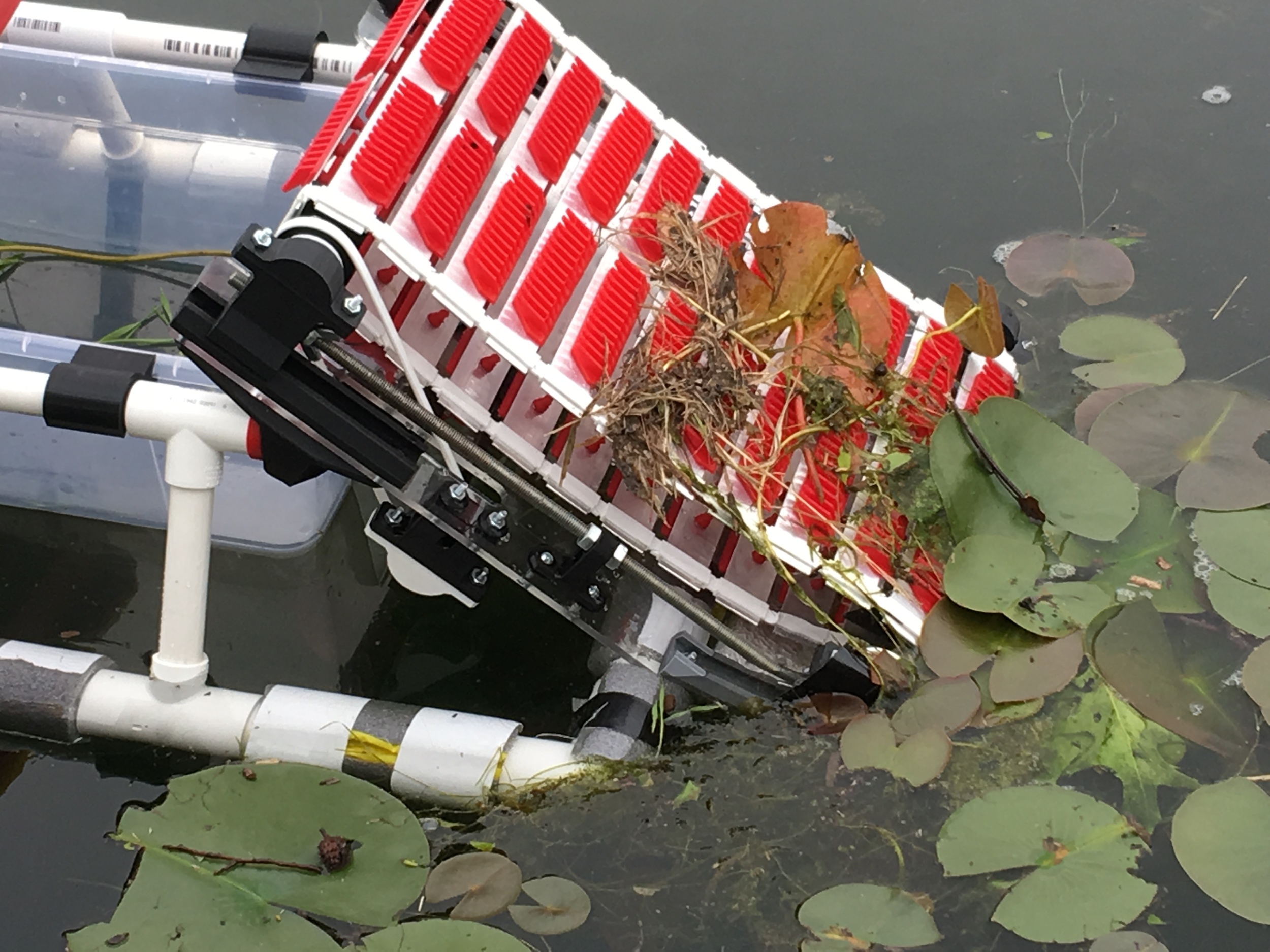
We found that Grim casually brushed by the lily-pads that were still tethered to the bottom of the lake, while picking up algae and plants that were already floating on the surface:
And here's a slow-mo of the paddle wheels, just for fun. GPS mode:
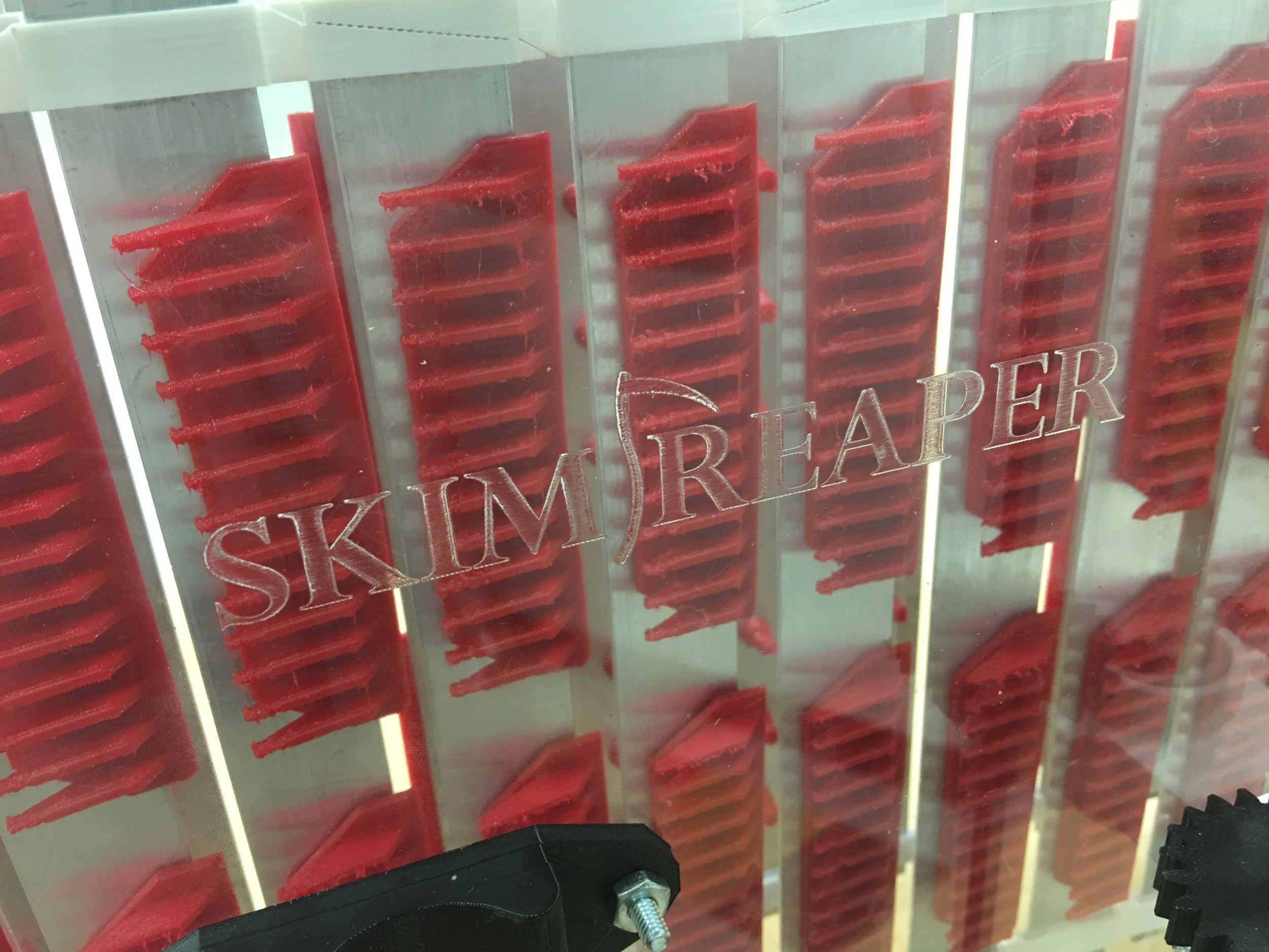
So armed with a GPS-guided algae seeking robot, we gave Grim makeover for Design Day. For a while, we were using an MDF board to mount all the conveyor components, but we laser-cut an acrylic plate with the SkimReaper logo. We 3D printed a template and spray-painted the logo on the lid to the electronics box, and we spray-painted all the PVC with a Maryland color scheme.


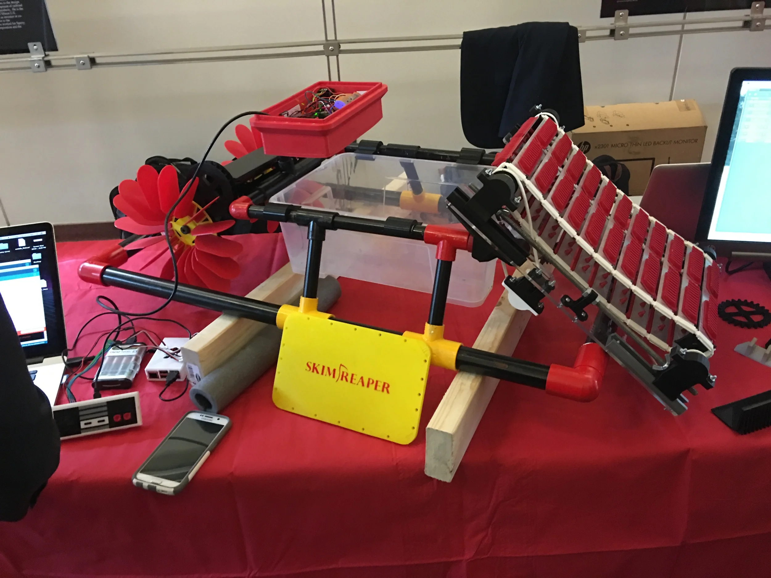
Grim then made an appearance at booth 19 at Design Day, looking sharp as ever:
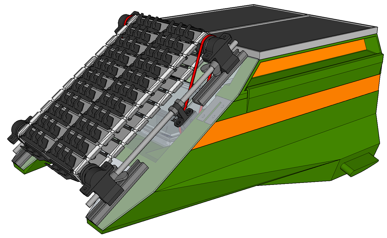
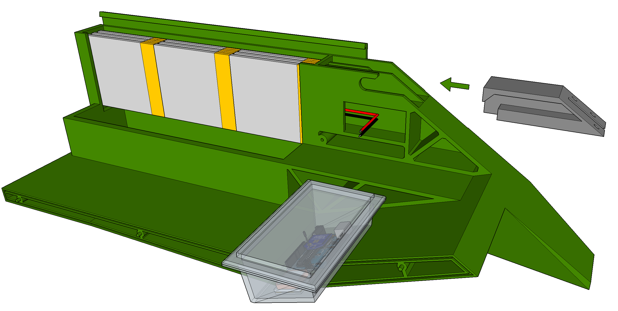
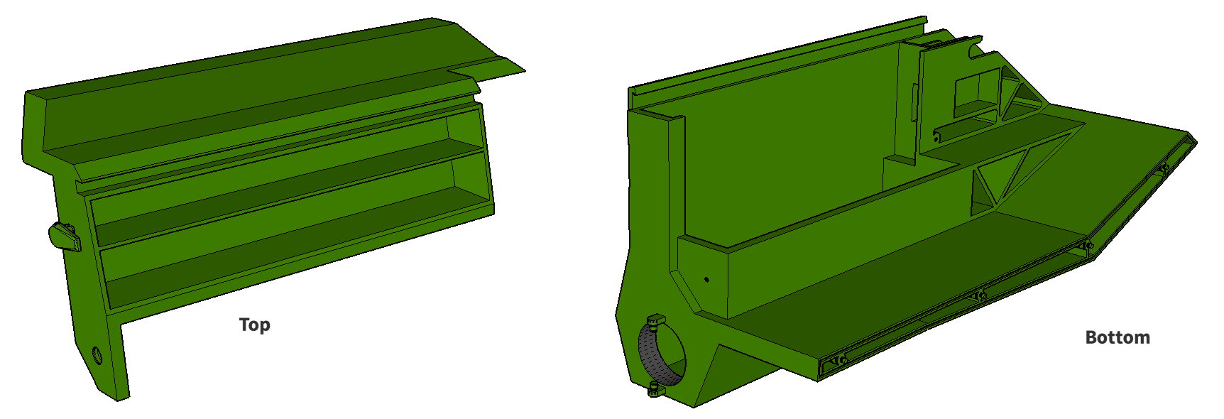
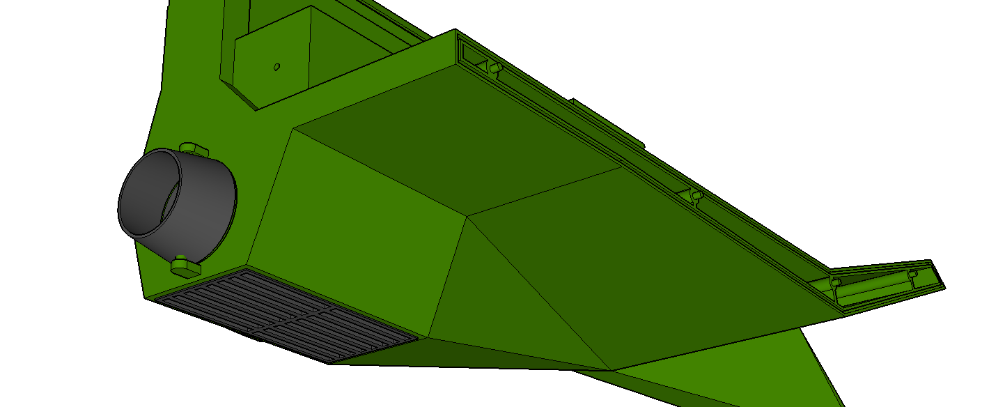
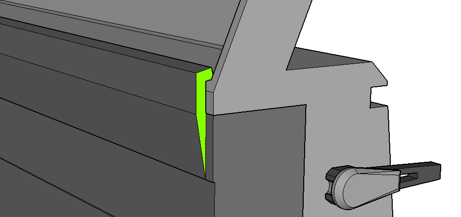
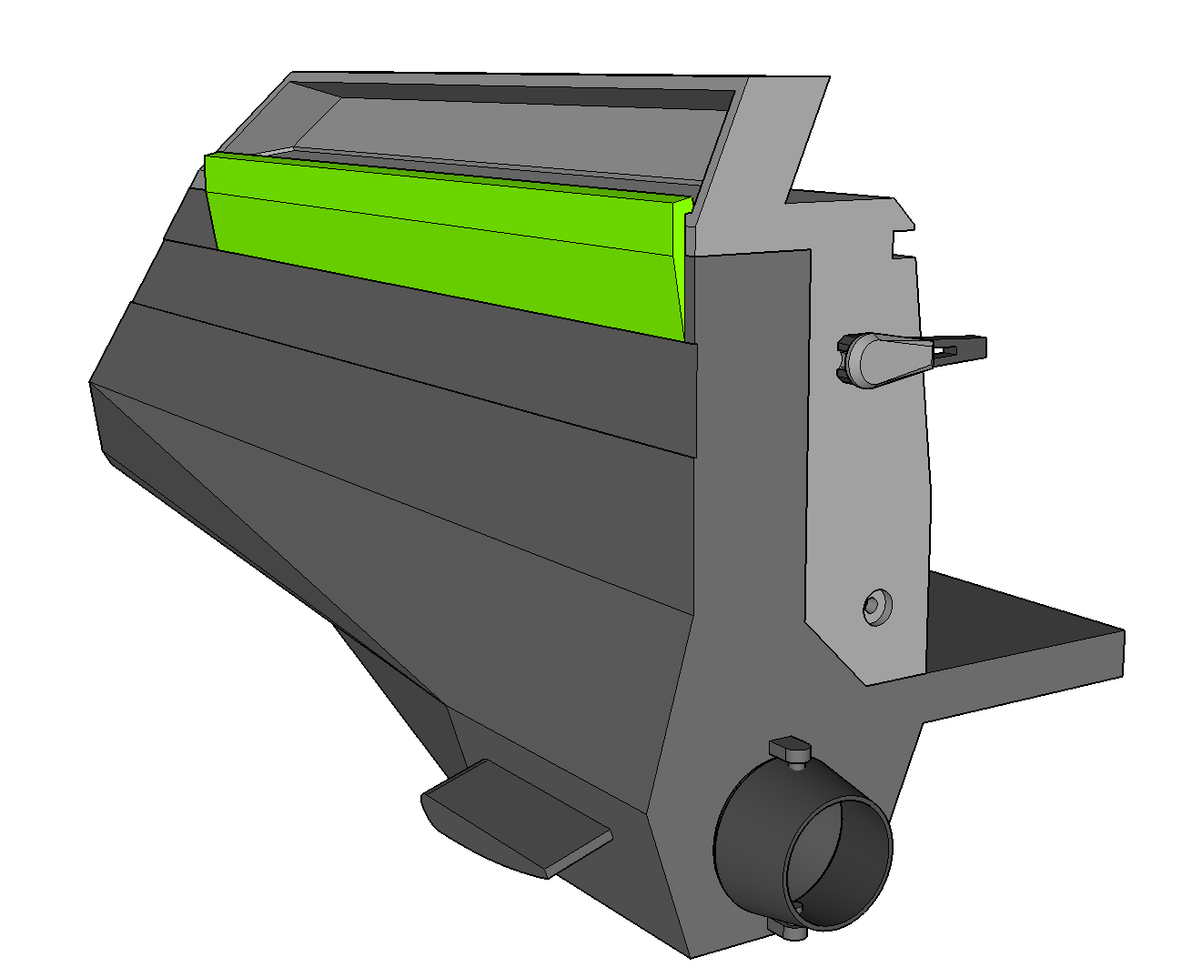
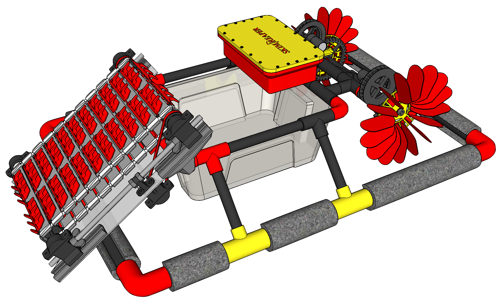
And now, as promised, I'll drop in some purdy renderings, FEA, and videos. The renderings are of a production version we designed. Every component was redesigned from the ground up in Fusion 360 for DFM/DFA, to be more robust, and to improve aesthetics. We also included some components like the solar panels that weren't in our prototype due to budgetary constraints. The chassis and most other parts were designed for injection molding, and other parts would be machined, stamped, and laser-cut depending on the tolerances, strength, and complexity requirements. Here's the production version:
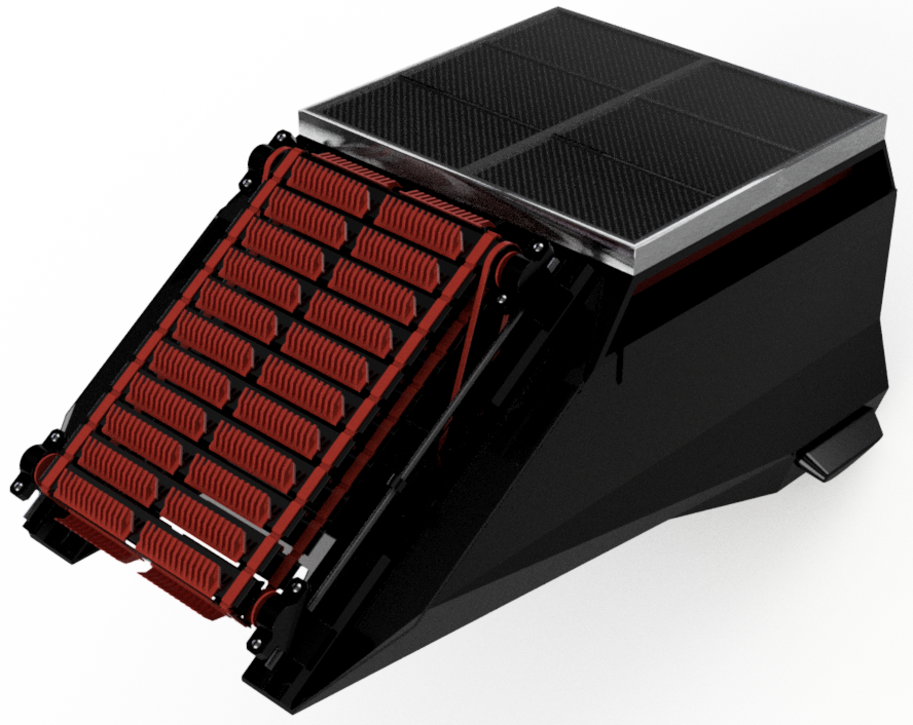
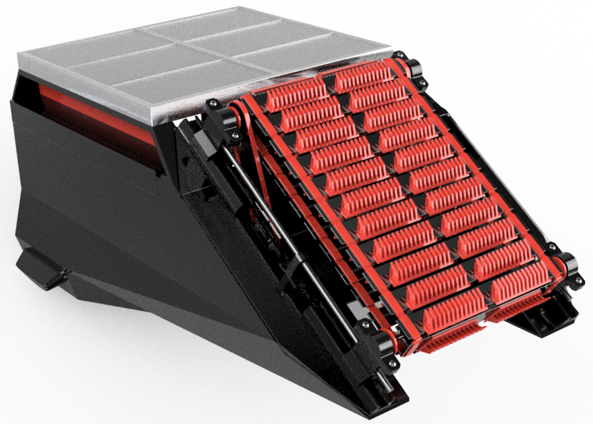
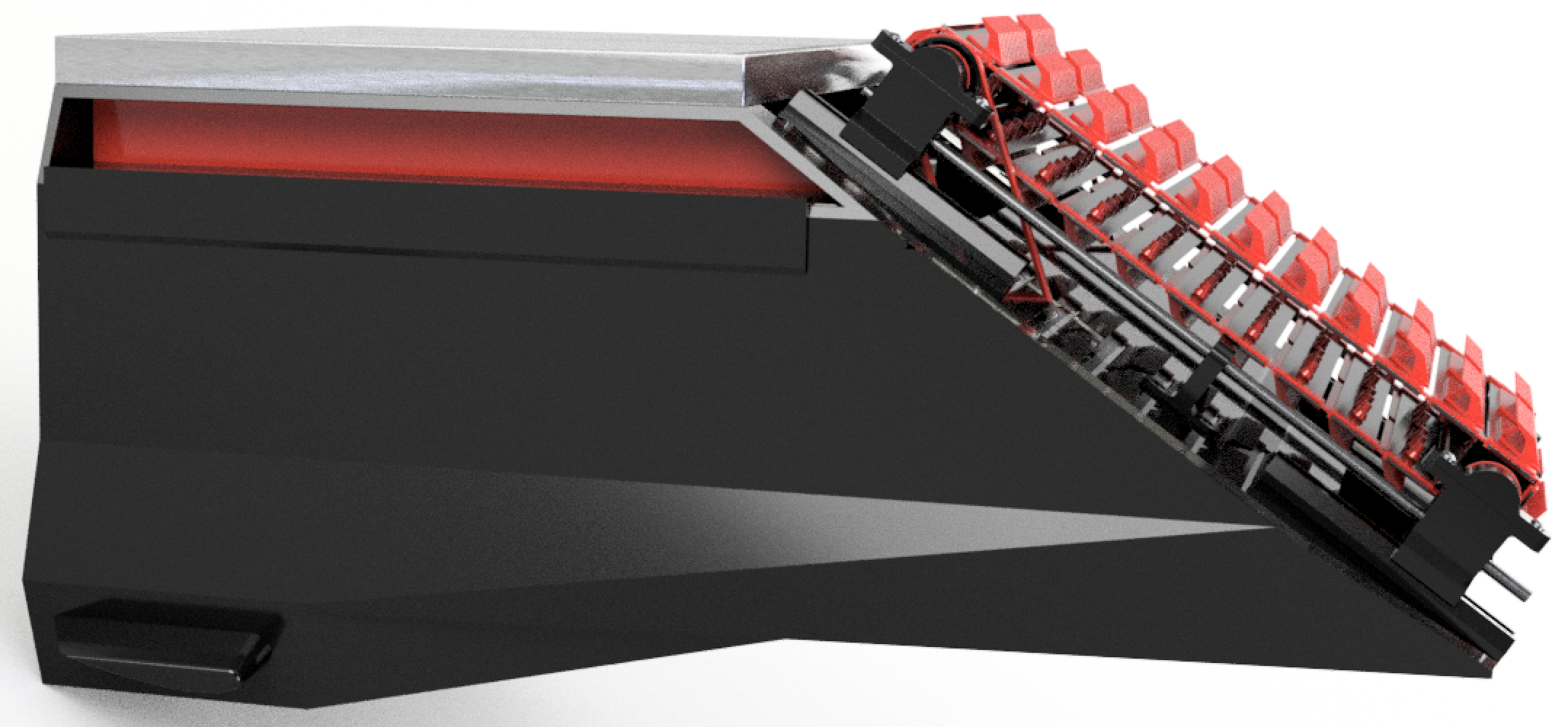
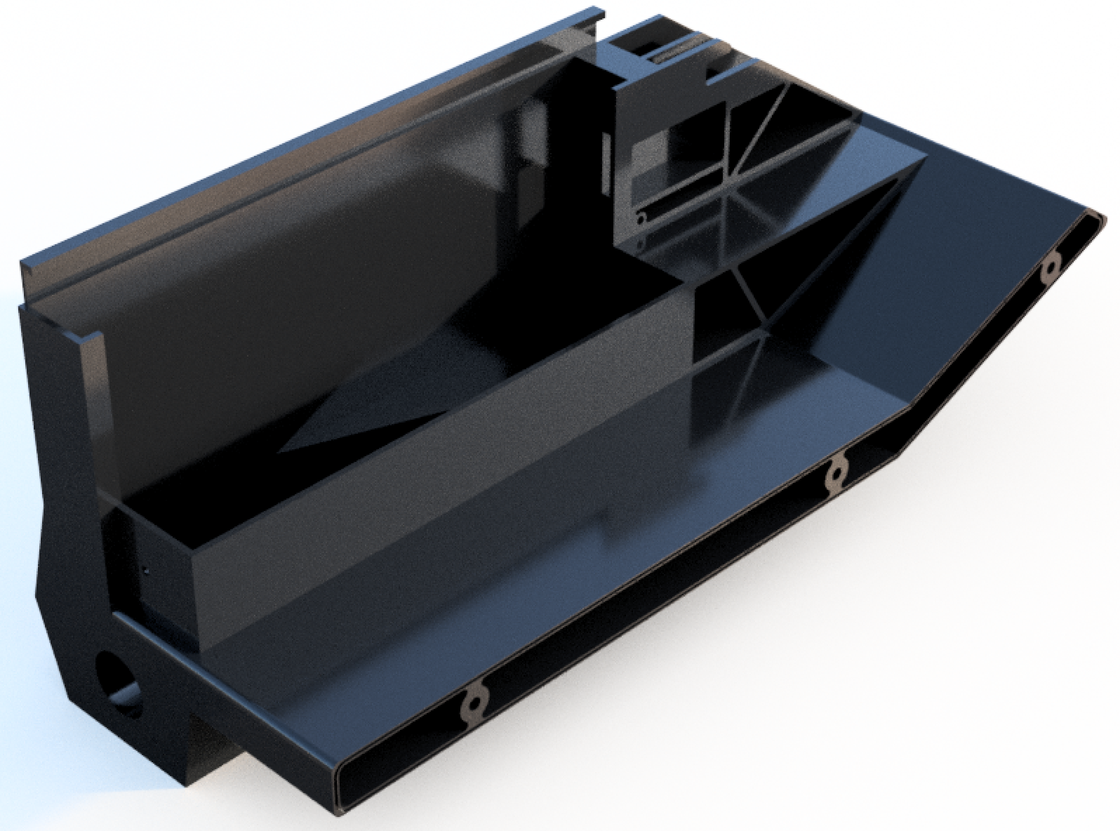
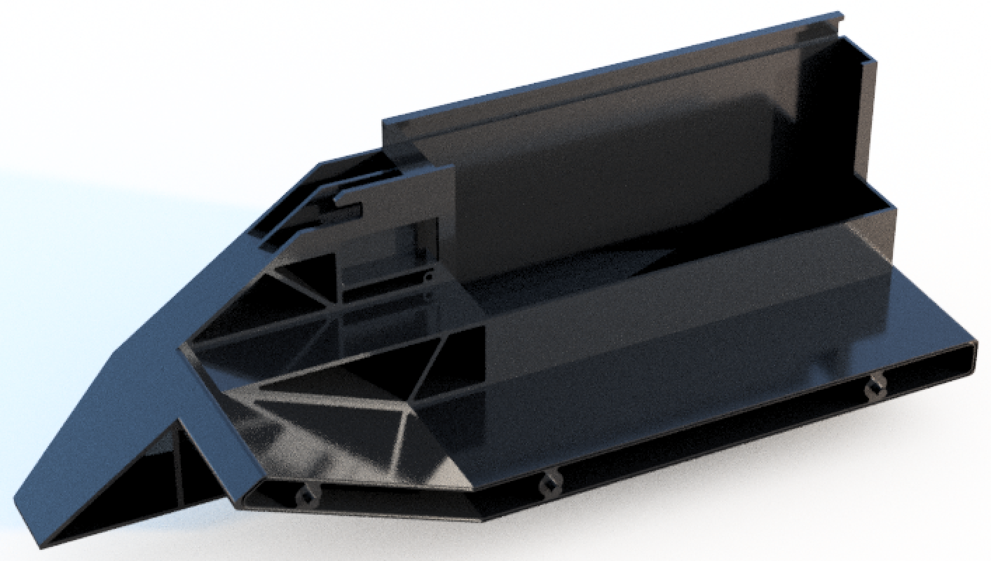
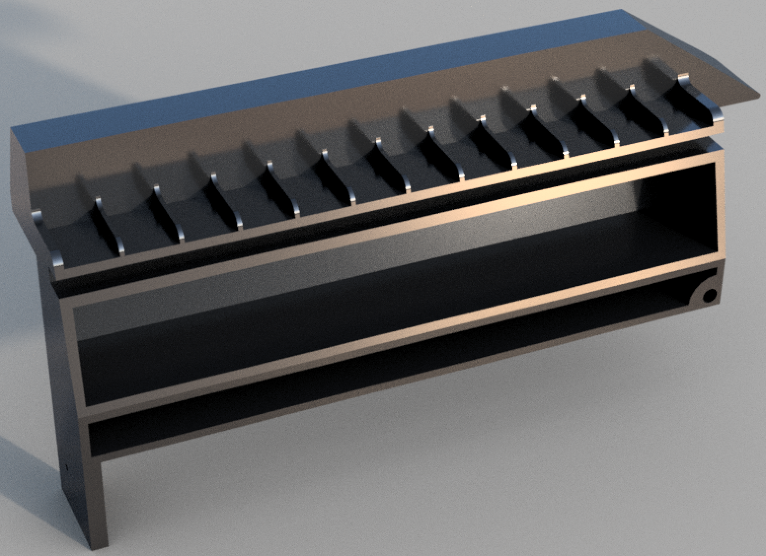
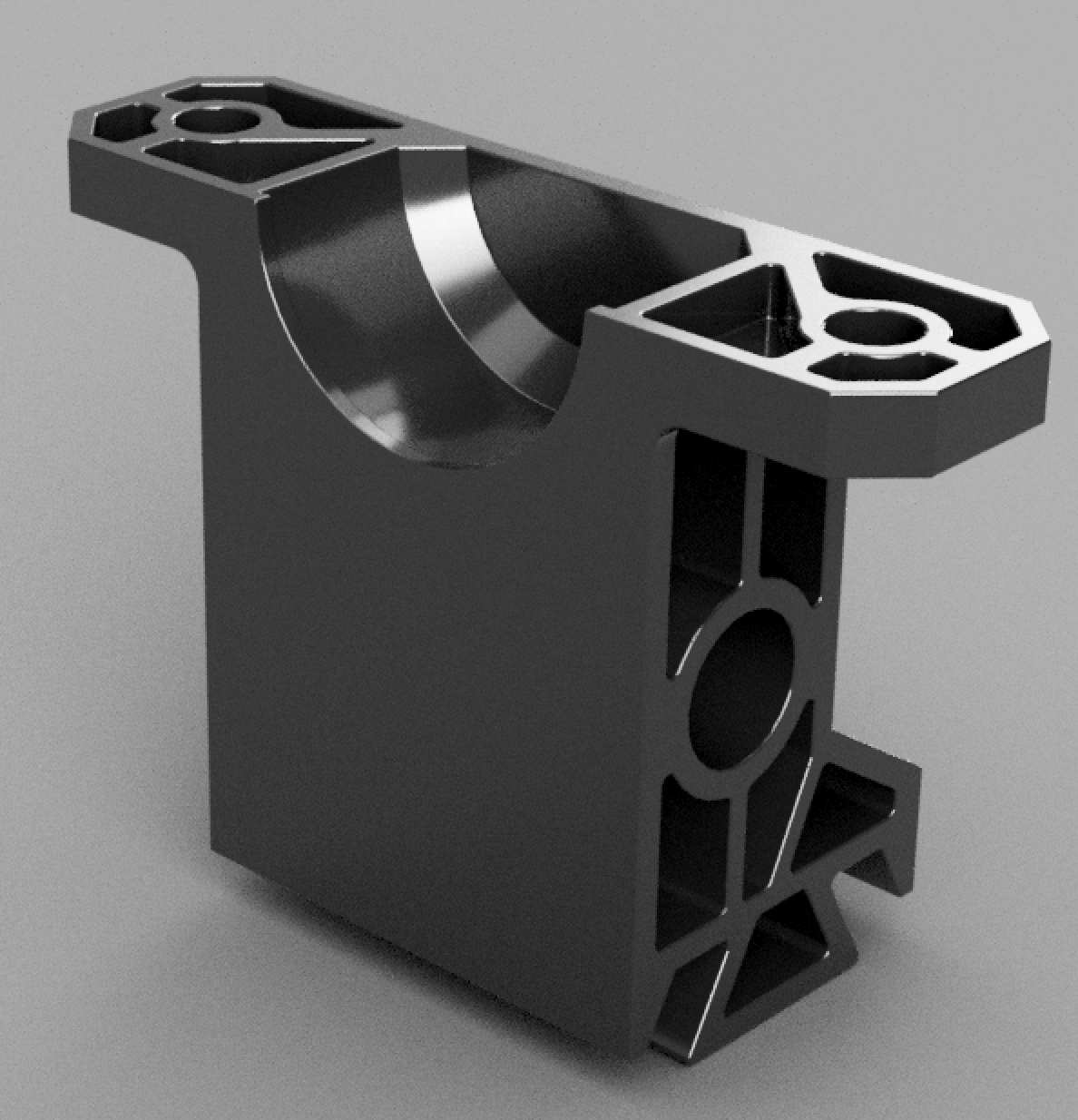
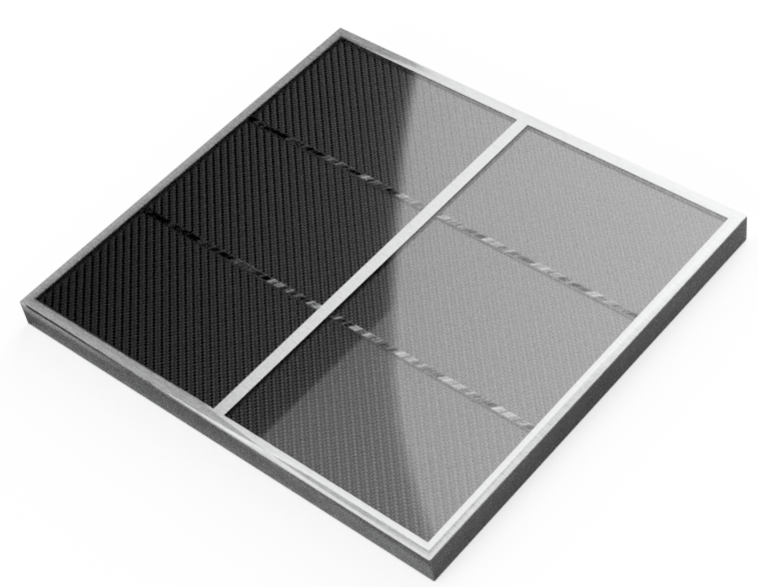
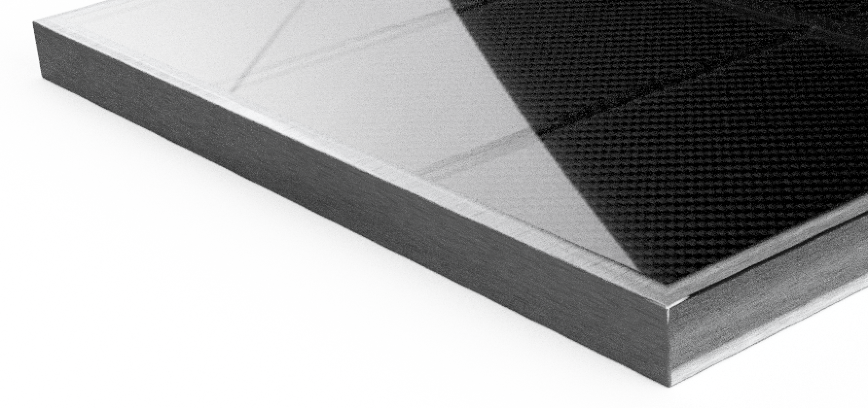
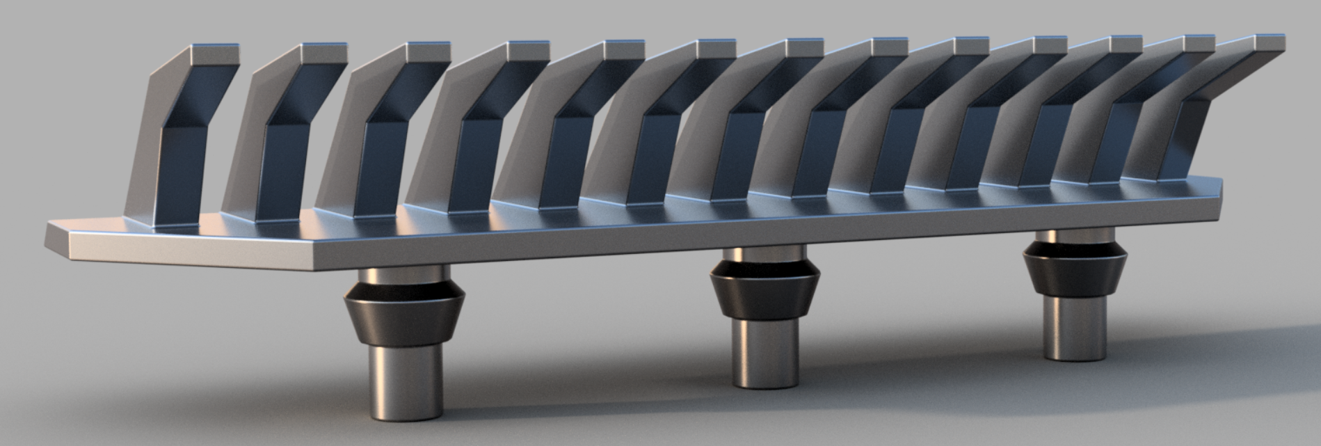
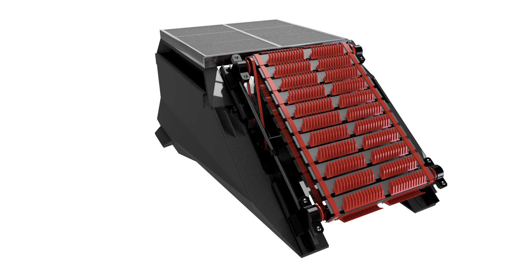
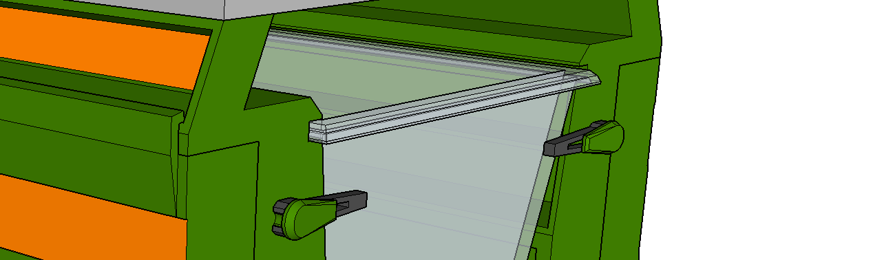
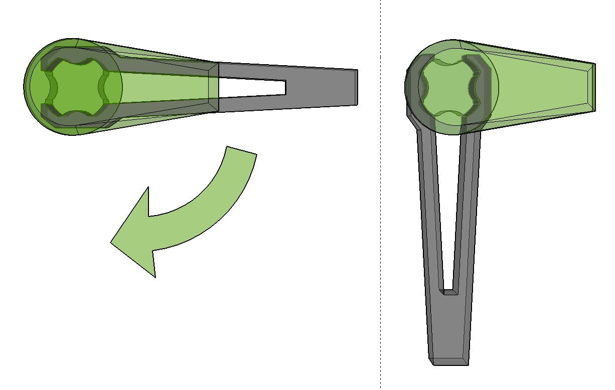
In those images, you can see some of the DFM features, uniform wall thicknesses and such, and we also ran crude draft and flow analysis on many parts. A fair amount of thought was also put towards minimizing the complexity and number of molds needed. Many parts only needed a simple A/B mold, and could even be part of a family mold to reduce costs further. For DFA, we designed slots and spaces for all major components, and cable management was designed to be molded into the chassis. The chassis also assembles using a long hook along the side, that allows the bottom and top pieces to be joined using only two threaded fasteners, as shown below. For the end user, we added two-position clips to hold in the collection basket, for easy access.
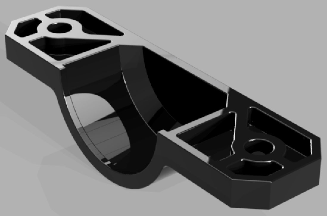
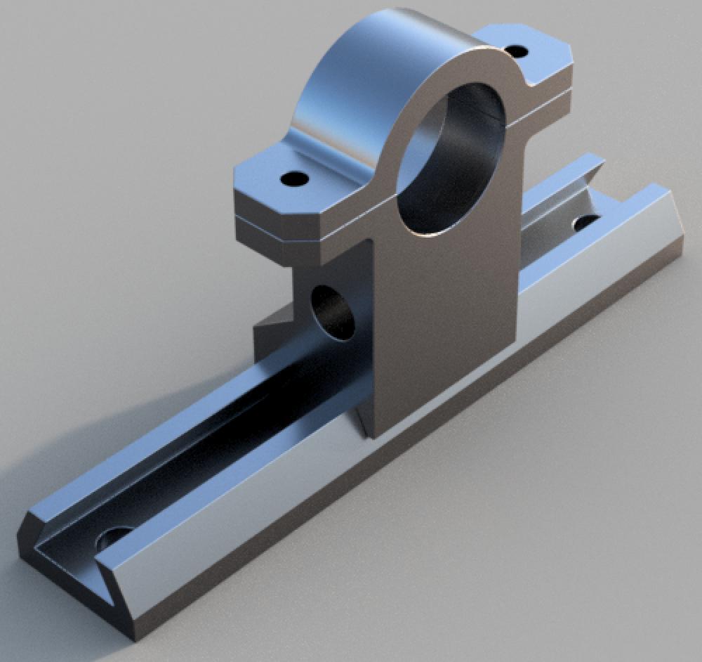
And here we have some snazzy-looking FEA:
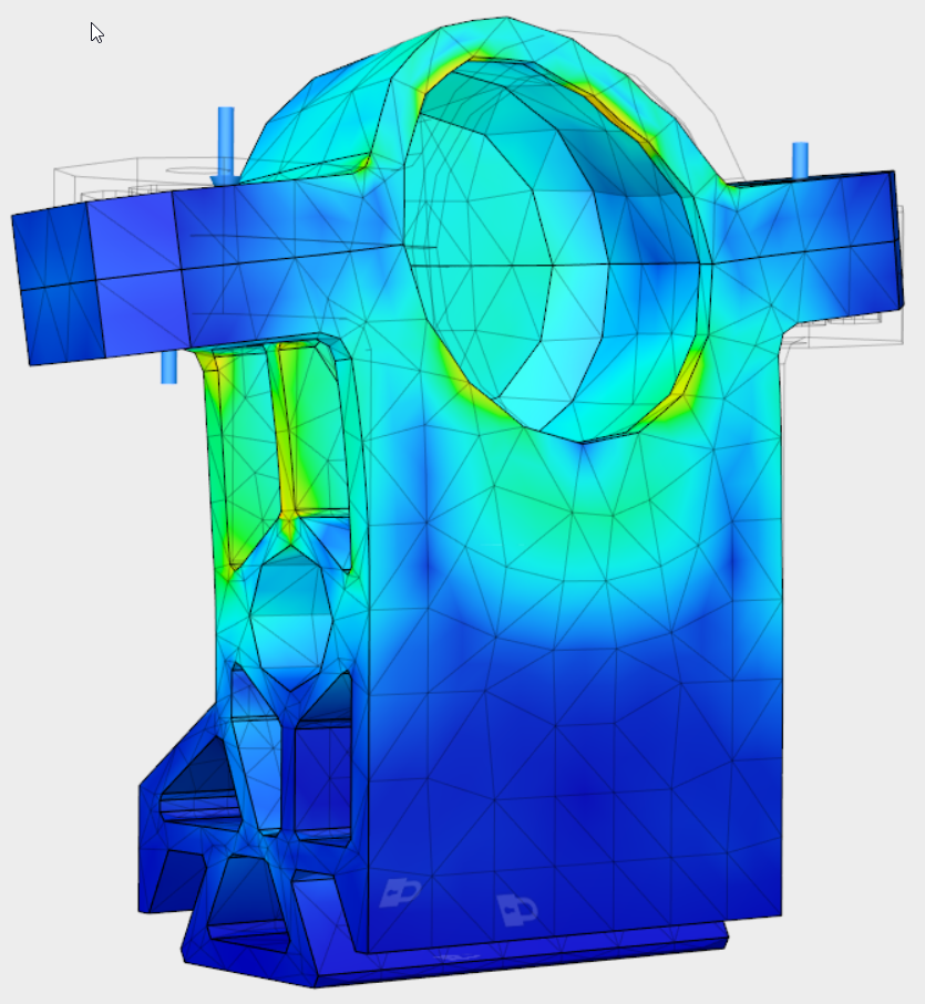
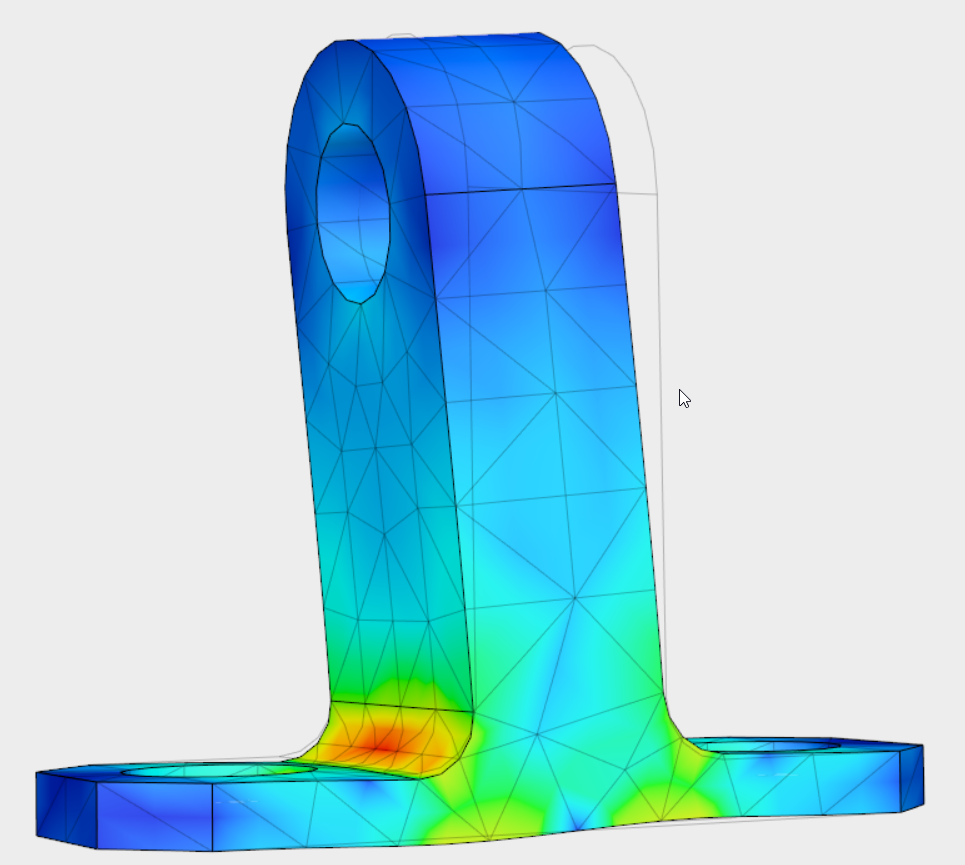
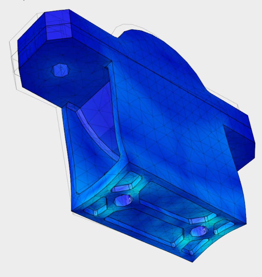
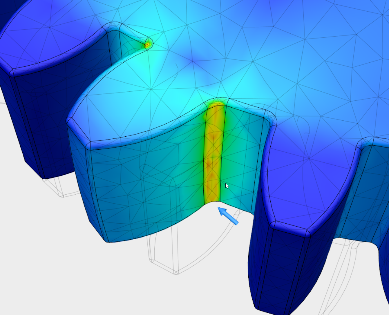
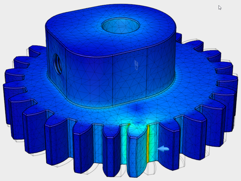
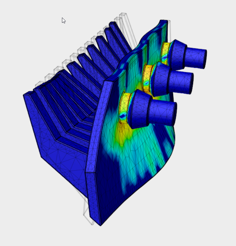
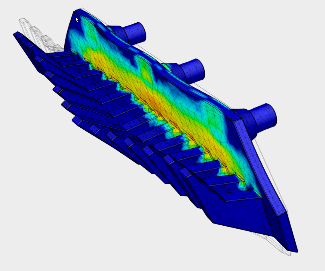

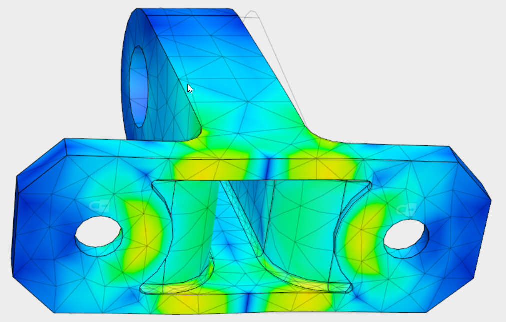
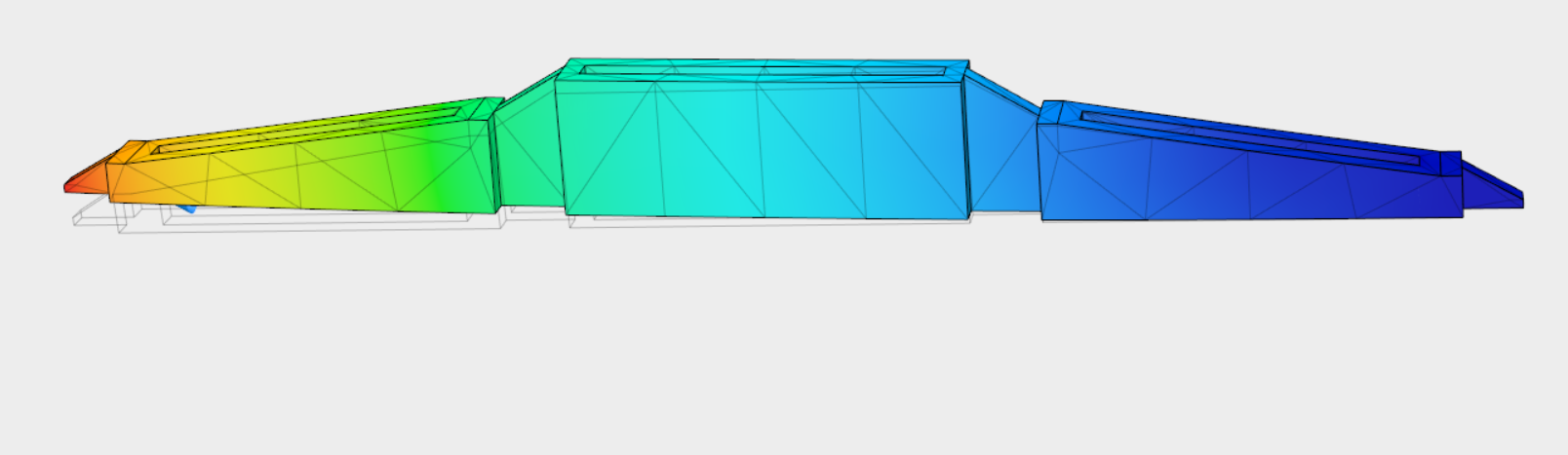
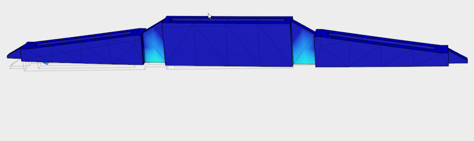
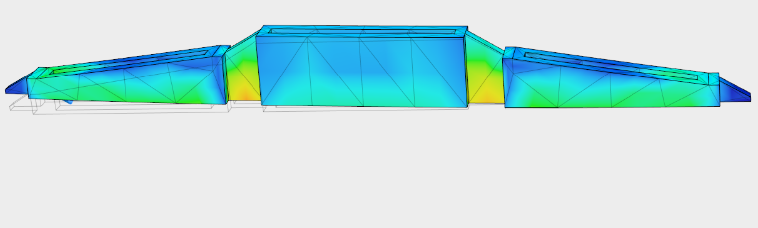
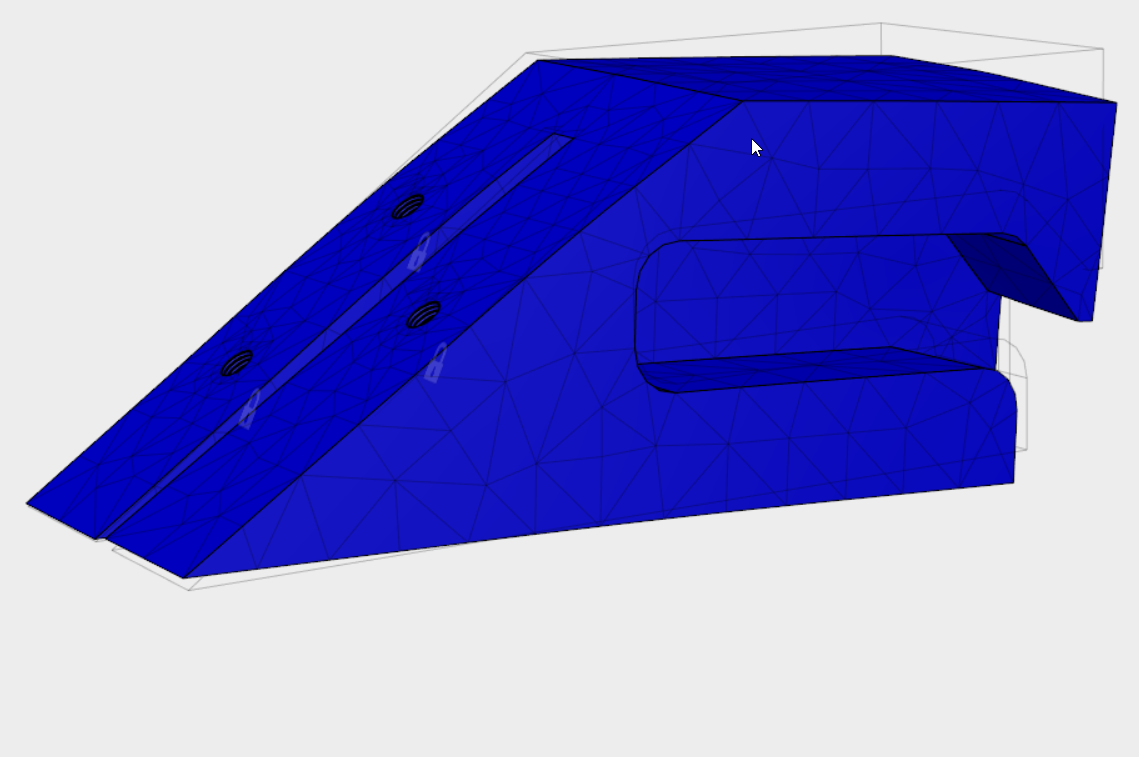
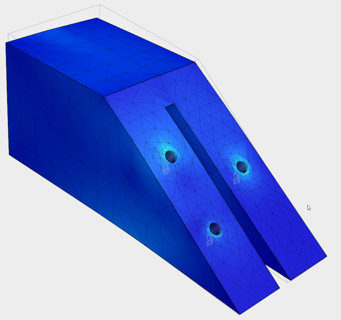
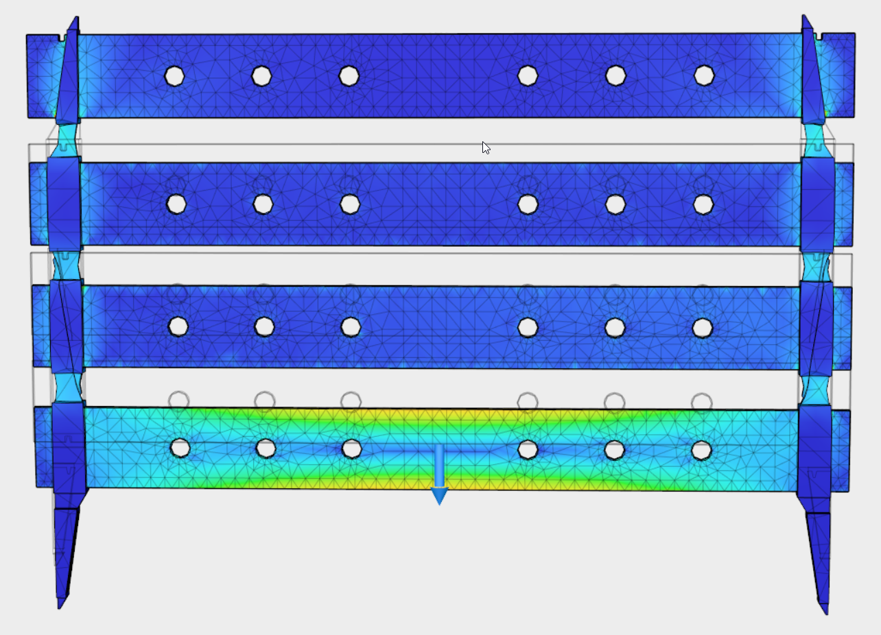
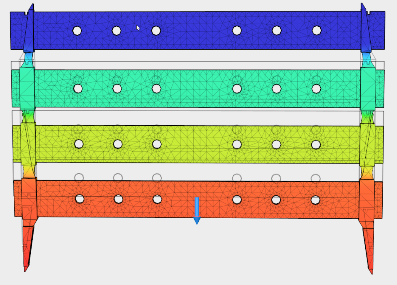
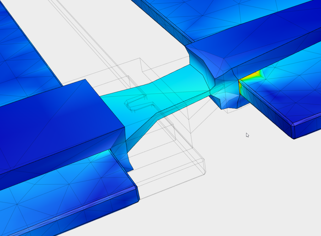
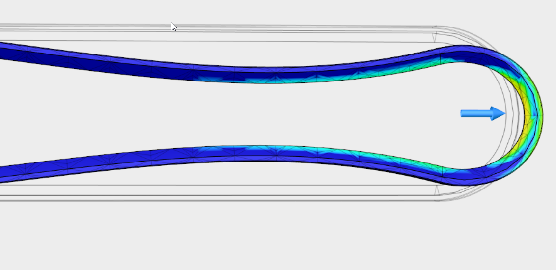
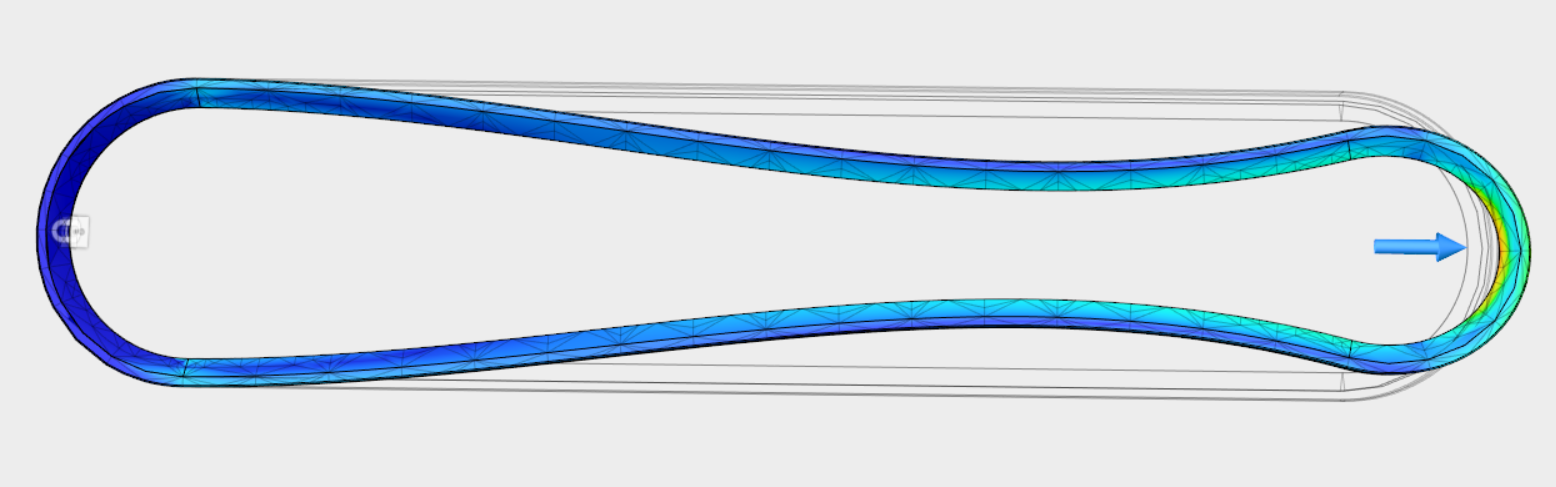
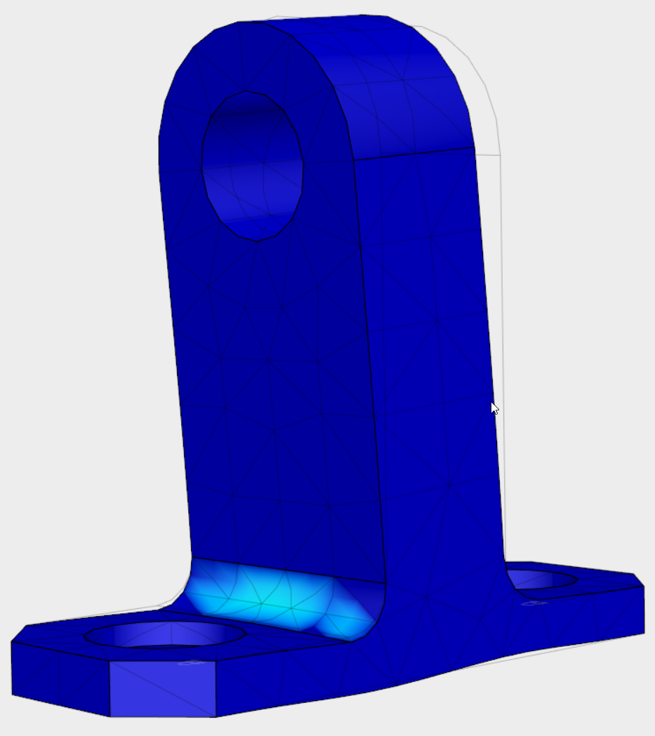
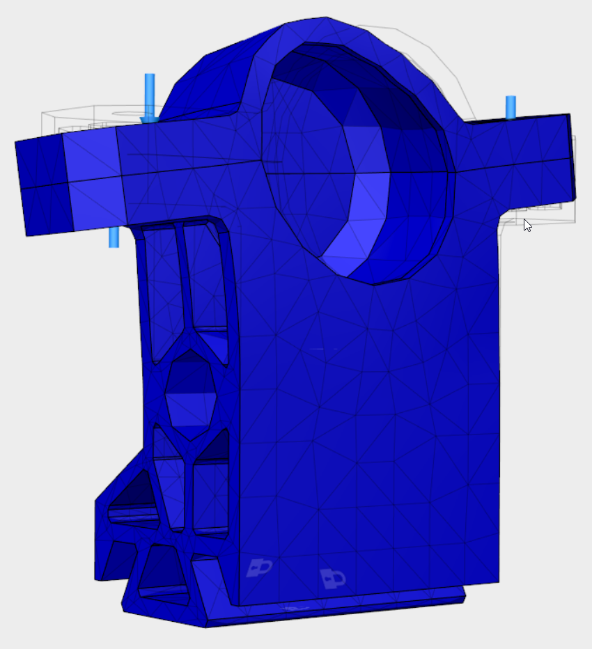
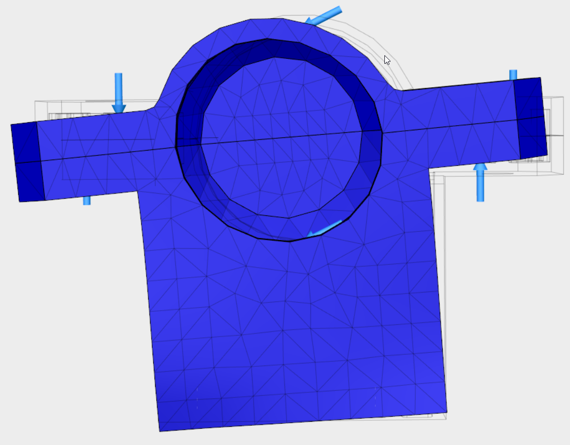
In case you're curious about the results, we found conclusively after many hours of work and by looking at many rainbowy pictures and complicated data that the conveyor assembly, which we fully assembled and tested prior to doing the FEA, will not break if we assemble and test it. Not particularly surprising there. I tried to break these parts (in FEA), but no dice. Most of them had safety factors well above 15 (the default highest value on the scale in Fusion 360), and that was under 2-4 times the expected loading conditions. The lowest SF on a rigid component was about 12, on the part shown in the second image, caused by a force that would be balanced in normal use. I took the force that would normally just be in compression along the axis of the threaded rod, and pretended like it would all be applied to one side of the rod holding bracket, unbalanced. Then I ran it at 4 times the expected load and got a SF of about 11.9. So I tried harder, and assumed that instead of "normal operation," we were dealing with an (intentionally?) abusive user. I pretended that the entire belt assembly was removed, leaving only the part in the second image holding the long threaded rods in place, and then the user lifted the entire vehicle by the end of the rod, creating a very large torsional force on the weakest component in the assembly, several orders of magnitude higher than what we would expect in normal operation and got: SF=2.32. Still no dice in the breaking department. In general, we made our prototype out of weaker materials than the final version, which will replace brittle acrylic sheeting with 1/4" Polycarbonate, 3D printed PLA with glass fiber reinforced Nylon 6/6 and so on, and the prototype is plenty strong and shows no signs of failure, so the "production version" will certainly be fine. So yeah, definitely not a waste of our time, and I'm definitely not bitter about it. At least it looks pretty. Maybe we'll do some fatigue testing and analysis later, and figure out the expected lifetime for the bearings we're running at a negligibly tiny fraction of their rated load. Or maybe we'll see how many times we can brush it with a feather before it disintegrates. All equally worthwhile.
Anyways, I'm gonna cut it out with all the words. Here's a cool exploded-view video of just the conveyor assembly:
And here's the CAD for the full assembly of our final prototype, plus the full exploded view video:
If you've read all the way to the bottom, thanks for your interest! If you have any questions, feel free to contact me, I (or someone on team SkimReaper) will definitely have an answer.
This project was created by a team: Travis Aion, Justin Albrecht, Steven Gresh, Caleb Hammer, Chris Sneeder, and me. Thanks guys!